Show Posts

This section allows you to view all posts made by this member. Note that you can only see posts made in areas you currently have access to.
Messages - Constantin

Pages: [1]
1
MP573 Microphone preamplifier / Re: General power check fails
« on: February 25, 2021, 09:58:21 PM »
Nothing to see here. I failed and reversed D4. Everything is working now that I corrected my mistake.

2
MP573 Microphone preamplifier / Re: General power check fails
« on: February 25, 2021, 09:46:53 AM »
A 1.636
B 2.808
C 13.06
D 7.39
E 1.06
F 6.75
G 0.00
H 1.07
I 0.00
J 0.423
K 0.423
L 0.007

3
MP573 Microphone preamplifier / General power check fails
« on: February 25, 2021, 01:33:12 AM »

Hello JP,

after successfully building the first MP573, I have problems with the second MP573:

The new module has no short circuit
The general power check only delivers 14.08 V DC between V+ and TP2

Can you point me in any direction? 

4
EQ573 Equaliser / Re: Placement of Capacitors Ceramic (docs-20)
« on: January 06, 2021, 01:19:01 PM »
Thank you!

5
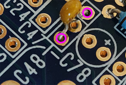
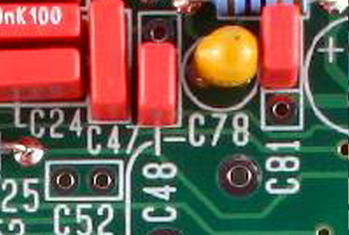
EQ573 Equaliser / Placement of Capacitors Ceramic (docs-20)
« on: January 06, 2021, 10:54:19 AM »
Are these the correct holes for C48 with Capacitor Ceramic for version docs-20 (center hole empty)?


This is the placement at C48 (also C80, C88) in the manual:


Best,
Constantin


6
CP4500 Stereo Bus Compressor / Re: 9db less output on the right channel
« on: January 05, 2021, 07:48:11 PM »
Hi JP,

I have bought 2-Propanol Alcohol and cleaned the PCB thoroughly. Both channels have the same output now. Sorry for keeping you busy with this thread. I was pretty sure that I had no problems with conductive flux, because Felder stated on their own website that the flux in their led-free solder was non-conductive. Now I am not sure if some solder particals might have stuck to the flux or what the problem might have been. I was pretty thorough in brushing the PCBs after assembly.

Well, lesson learned: always clean off flux, even if the producer advertises it as non-conductive and non-corrosive ("no clean").

Thank you for your support!
Constantin

7
CP4500 Stereo Bus Compressor / Re: 9db less output on the right channel
« on: January 05, 2021, 04:58:27 PM »
Yes, it is resting at 0.

I also used solder with non-conductive flux (at least that is what Felder states on the website):
https://www.felder.de/products/electronic-applications/wave-soldering-selective-soldering/nige-solder-sn100ni-snag-sn100c/loetdraht-iso-core-clear-5552941030.html

8
CP4500 Stereo Bus Compressor / Re: 9db less output on the right channel
« on: January 04, 2021, 09:25:05 PM »
Hi JP,

All values are ok except these:

Channel 1 (I plugged the testconnector into channel 1)
input signal = 3VAC
Threshold on +15
Makeup on 0
Signal level (VAC) on TP2=1.4VAC


Channel 2 (I also plugged the testconnector into channel 2)
Input signal = 3VAC
Threshold on +15
Makeup on 0
Signal level (VAC) on TP7=2.05VAC, TP9=1.35VAC
DC voltage (VDC) on pin 1 (white dot) of U16 (-0.018V).

Input signal = 3VAC
Makeup on 0
Threshold on -15
DC voltage (VDC) on pin 1 of U16 (white dot) = -0.18VDC.

9
CP4500 Stereo Bus Compressor / 9db less output on the right channel
« on: January 04, 2021, 06:36:29 PM »
No matter how I set the threshold or the makeup...
  • the right channel always has 9db less output than the left channel
  • only when I switch the unit off, both channels have identical output
I have changed cables and the position within the lunchbox.

Does anyone have a clue where to start measuring?

Thank you, Constantin

Pages: [1]